Latest Entries »

Latest Embedded Projects

Final Year Projects List from

http://projectsbazaar.in

.Project Name

  • 1   RFID BASED ACCESS CONTROL SYSTEM……………………………………12000/-
  • 2   THUMB SCANNER BASED ATTENDANCE SYSTEM………………………… 16000/-
  • 3   HOME SECURITY SYSTEM WITH GSM ALERTING (using GSM modum)….16000/-
  • 4   SPEECH RECOGNITION BASED SECURITY SYSTEM……………………12000/-
  • 5   RFID BASED ID RECOGNITION SECURITY SYSTEM……………………..12000/-
  • 6   ALCOHOL AND LPG BASED BLACK BOX WITH GSM ALERTING………………16000/-
  • 7   Speech Based Robotic Car………………………………………………………….12000/-
  • 8   GPS based navigation system…………………………………………………………16000/-
  • 9   Vehicle anti-collision using IR signals.…………………………………..9000/-
  • 10  Controller Area Network ………………………………………………………9000/-
  • 11  Finger print based Evm……………………………………………….. 14000/-
  • 12  IVRS for colleges and schools…………………………………………. 14000/-
  • 13  Railway Accident Monitoring System (using RFID)…………………16000/-
  • 14  Bus fare pay system for passengers ………………………………..14500/-
  • 15  Gas detection robot……………………………………………..14500/-
  • 16  RFID BASED Person  Identification Device …………………9500/-
  • 17  Auto irrigation robot…………………………..12,000/-
  • 18  RFID Based Local Vehicle Tracking System………………….9900/-
  • 19. REGENERATIVE   BRAKING SYSTEM………………..11900/-
  • 20  STEERING CONROLLED HEADLIGHT…………………9900/-
  • 21  HYDRAULIC BRAKING SYSTEM FOR CAR/IND. APPLICATION……….9000/-
  • 22. TELEMEDICINE SYSTEM(gsm)…………………………….16000/-
  • 23  Smart Card  identification system………………………………………9000/-
  • 24  RFID Tag Based Car Parking with Automatic Prepayment System-  Price on Demand
  • 24  RFID Based Automatic Toll Tax Collection  Price On Demand
  • 25 To Implement Your Idea Into a Project Feel Free to mail Us at Our Contact Mail.

Regard’s Team

ProjectsBazaar.in

http://projectsbazaar.in/embedded.html

Flat Discount on Advance Booking Only


Embedded Projects List Wit Price for Final Year Students of Engineering B Tech EC,EI,AI,ELECTRONICS,COMMUNICATION,INSTRUMENTATION,APPLIED INSTRUMENTATION BSC ELECTRONICS PROJECT,PROJECTS FOR EMBEDDED,Embedded systems Projects,ECE Projects,Electronics Projects,Ieee Projects,Ieee embedded Projects,Ieee Project,embedded based Projects,embedded project,Embedded System,Embedded systems,Projects in Embedded ,Projects using Embedded,projects on Embedded,Embedded systems projects,embedded system projects,embedded system embedded project

Micro Controller Based Projects,electronic projects,electronics project,electronics projects,embedded based projects,embedded projects,final year projects,mini projects,major projects,projects on microcontroller,8051 projects

VHDL Project’s List

with Rating


  • 1    DESIGN AND IMPLEMENTAION OF BIST(BUILT IN SELF TEST) FOR RAM       (GOOD)

  •       BIST is the capability of testing chip by itself. The key idea of BIST is to place a test pattern generator and a test data

  •       evaluator. BIST has many advantages over the traditional testing method. the program has been carried out for testing

  •       RAM and VHDL codes written for each block.

2   STEPPER MOTOR DRIVER                             (SMALL)

     A microprocessor lab needs a universal interface to drive a stepper motor. in order to experiment with microcontroller driving

    stepper motor it would be useful to have a single universal interface IC wired to stepper motor. This circuit needs to accept any

     of the typical forms of stepper motor drive signals from microcontroller and activate the windings of the motor to make it move

      in desired manner

3   KEYPAD ENCODER                (SMALL)

     A Digital circuit that encodes a hexadecimal keypad into a four bit binary output.

4   DIGITAL CLOCK    (GOOD)

     A time clock that displays the time of day in hours, minutes, and in seconds.

5  VITERBI  DECODER            (VERY GOOD—BIG)

    The Viterbi decoding algorithm proposed in 1967 is a decoding process for convolutional codes. Convolutional coding has

    been used in communication systems including deep space communications and wireless communications. Convolutional

    codes offer an alternative to block codes for transmission over a noisy channel. Convolutional coding can be applied to a

    continuous input stream (which cannot be done with block codes), as well as blocks of  Data

6   Wallace Tree Multiplier           (GOOD)

     Wallace Tree Multiplie is considerably faster than a simple array multiplier because its height is logarithmic in word size, not

     linear. However, in addition to the large number of adders required, the Wallace tree’s wiring is much less regular and more

     complicated. As a result, Wallace trees are often avoided by designers, while design complexity is a concern to them.

7   DIFFERENT TYPE OF MULTIPLIER

8  LANDLINE SWITCHING SYSTEMS  [ONE WAY    (SMALL)     OR    MULTIWAY        (VERY GOOD)]

     This project was designed to develop a VHDL code which would perform three basic functions of an electronic switching

     system to transmit signals over the connection or over separate channels to convey the identity of called and the calling

     address,and alert the called station; to establish connections through a switching network for conversational use during the

    entire call; and to process the signal information to control and supervise the establishment and disconnection of the

    connection We considered a group of eight subscribers between whom we had to establish the connection. We used the

     behavioral modeling of VHDL to implement the switching system. We used array structures for control, data and caller id

    memories while SS7 protocol was used for signal transmission through the switching network,Thus both the single way and

    multi way landline switching systems were successfully implemented through VHDL. Hence the project enabled us to design

    ICs for a landline switching system.

9  HAMMING CODE FOR ERROR DETECTION AND CORRECTION   (GOOD)
Richard Hamming found a beautiful binary code that will correct any single error and will detect any double error (two separate
errors). The Hamming code has been used for computer RAM, and is a good choice for randomly occurring errors. (If errors
come in bursts, there are other good codes.)

10   4 BIT OR 16 BIT MICROPROCESSOR  (GOOD)

11   TRAFFIC LIGHT CONTROLLER (SMALL)

       Traffic light controller, we can be used to control the function of traffic-light signal on the main road.In this controller, we have

      three mode –

     1. > Regular:- States each with an independent programmable time passed to the circuit by means of constant.

     2. > Test :- In Test mode all preprogrammed timers to be overwritten with a small value such that the system can be easily

            tested during maintenance. This value should be programmable and passed to the circuit using a constant.

     3. > Stand by :- If set the system should activate the yellow light in both direction and others remain off so while the stand by

            signal is active.

12   8 BIT SIGNED MAGNITUDE ADDER                                 (SMALL)

13   VENDING MACHINE                          (SMALL)

SYNOPSIS

AIM

DESIGN & IMPLEMENTATION OF A

PRE-PAID ENERGY METER


By : Projectsworld Team


INTRODUCTION

OBJECTIVES:-


  • To Design a circuit of an electronic power saving pre-paid energy meter.
  •  Develop new ideas to implement this circuit purposely.
  • To study the circuitry and different types of components &  opto-coupler, 89c51 microcontroller, relay, IR-LED, photodiode and programming in assembly language .


A scheme of Electricity billing system called a PREPAID ENERGY METER WITH TARIFF INDICATOR can facilitate in improved cash flow management in energy utilities and can reduces problem associated with billing consumer living in isolated area and reduces deployment of manpower for taking meter readings.

Every consumer can buy a memory card. The memory card is available at various ranges (ie. Rs 25, Rs 50, Rs 150 etc).In our project we have given the name for memory card as smart card.
When the consumer insert a smart card into the card reader which is connected in prepaid energy meter with tariff indicator kit. Then the card reader will read the stored information using the MC program. So that the smart card cannot be reused by others. Suppose if a consumer buy a card for Rs.25/- he / she can insert this amount through the card reader so that prepaid energy meter with tariff indicator kit will be activated. According to the power consumption the amount will be reduced. When the amount is over, the relay will automatically shutdown the whole system. In our project we also have a provision to give an alarm sound to consumer before the whole amount is reduced.

NEED TO SAVE THE ENERGY:

  1. The saving of energy will help our country to develop economically and socially.
  2. The energy which is wasted can be utilized somewhere in the remote area.
  3. It is also very helpful in our life to reduce the electricity bill.

HOW CAN WE HELP IN SAVING THE ENERGY?

We can save energy by using the electrical appliances only when needed. So the appliances should be switched off when you are not using them. Generally what happens:-

  1. We are not in the room and the appliances like bulb, tube lights, fans are switched ON mode.
  2. The AC, fans are ON when the temperature is quit low. This carelessness/ignorance not only wastes the energy but also have bad effect on your health.
  3. All the lights/bulbs are ON and only when the visibility light required.
  4. Leave the computers ON while we are not working on it means when we are reading book in front of it, gossiping, going for the lunch etc.
  5. Generally in our home some program is running and nobody is there to enjoy it.


BLOCK DIAGRAM

USED COMPONENTS

SEMICONDUCTORS

(1) IC-1 ………….. 7805 (Regulator)

(2) IC3-IC4…………. MCT2E (Opto-Coupler)

(3) IC-2………………… 89C51 (Micro-controller )

(4) D1-D2 …………….IN 4007

(5) LED ……………… Light Eammiting Diode

(6) T1-T4…………..(NPN)

(7) T5 …..………… (PNP)

(7) XTL…………….Crystal 11.0592 Mhz.

(8) LCD

(9) PHOTODIODE

(10) IR-LED

(11) BUZZER


RESISTOR

(1) R1-R3…………….1K OHm.

(2) R4-R19………….. 10K OHm.

(3) R20-R23 ……….. 100 Ohm.

(4) VR1 ………………. 1K OHm.


CAPACITOR

(1) C1…………. 1000uf.

(2) C2…………. 100 uf.

(3) C3………..10 uf.

(4) C4,C5 …… 33 PF

MISCELLANEOUS

(1) RL1 ………………. RELAY 6V \100 0Hm.

(2) S1 ……….……………… PUSH -TO- ON

(3) 9-0-9 …………………….STEP DWON TRANSFORMER.


REFERENCES

  1. EFY.
  2. http://www.projectsworld.wordpress.com
  3. www.IndianEngineer.tk
  4. www.indianengineer.in
  5. www.microcontrollerprojects.indianengineer.in


Please Confirm Your Booking by Paying your Booking amount at our Bank Account’s


Punjab National Bank A/c No:-

067400-1500035229

In Name of Sh Sumit Kumar.

Thank’s

Freshersblog@gmail.com


BLOCK DIAGRAM OF
SOLAR TRACKING SYSTEM


SCHEMATIC DIAGRAM OF
SOLAR TRACKING SYSTEM

READ TIME FROM RTC (REAL TIME CLOCK)AND CALCULATE REQUIRED ANGLE OF INCLINATION

MEASURE PRESENT INCLINATION ANGLE THROUGH POSION OF 10K/OHM VARIABLE RESISTOR

IF POSITION SOLAR PANNEL IS NOT CORRECT ROTATE THE STEPPER MOTOR TO CORRECT THE POSITION

PANNEL VOLTAGE AND PANNEL CURRENT IS ALSO DISPLAYED ON LCD

THIS PROJECT IS AVAILABLE  IN BOTH SINGLE & dOUBLE ROTATION.


RFiD Based Door Access Control

RFiD Based Door Access Control

SYNOPSIS

The concept of access control is brought about using a card, a corresponding card reader and a control panel interfaced with the server. The card is a proximity card with a unique identification number integrated in it. The reader reads the data and sends it to the control panel, which is the micro controller. This controller checks the validity of the data with the server, which bears the database. The server is loaded with the details about the employee for that number.

The control panel checks whether he/she is allowed to enter the particular door or not. If the employee is authentic, then he/she is allowed access in the particular entrance.

The employees can be permitted in a given entrance as per his/her designation. The access control is employed at this point. When a person of a particular designation is not supposed to be allowed in a given entrance.

CIRUIT DIAGRAM

rfid based access system ckt

Radio frequency (RF) refers to electromagnetic waves that have a wavelength suited for use in radio communication. Radio waves are classified by their frequencies, which are expressed in kilohertz, megahertz, or gigahertz. Radio frequencies range from very low frequency (VLF), which has a range of 10 to 30 kHz, to extremely high frequency (EHF), which has a range of 30 to 300 GHz.

RFID is a flexible technology that is convenient, easy to use, and well suited for automatic operation. It combines advantages not available with other identification technologies. RFID can be supplied as read-only or read / write, does not require contact or line-of-sight to operate, can function under a variety of environmental conditions, and provides a high level of data integrity. In addition, because the technology is difficult to counterfeit, RFID provides a high level of security.

RFID is similar in concept to bar coding. Bar code systems use a reader and coded labels that are attached to an item, whereas RFID uses a reader and special RFID devices that are attached to an item. Bar code uses optical signals to transfer information from the label to the reader; RFID uses RF signals to transfer information from the RFID device to the reader.

Radio waves transfer data between an item to which an RFID device is attached and an RFID reader. The device can contain data about the item, such as what the item is, what time the device travelled through a certain zone, perhaps even a parameter such as temperature. RFID devices, such as a tag or label, can be attached to virtually anything – from a vehicle to a pallet of merchandise.

RFID technology uses frequencies within the range of 50 kHz to 2.5 GHz. An RFID system typically includes the following components:

• An RFID device (transponder or tag) that contains data about an item

• An antenna used to transmit the RF signals between the reader and the RFID device

• An RF transceiver that generates the RF signals

• A reader that receives RF transmissions from an RFID device and passes the data to a host system for processing

CLICK HERE TO SEE MORE PROJECTS

SCHEMATIC DIAGRAM
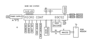
HOME SECURITY SYSTEM + SMS THROUGH GSM MODEM

SCHEMATIC DIAGRAM  HOME SECURITY SYSTEM + SMS THROUGH GSM MODEM

SCHEMATIC DIAGRAM HOME SECURITY SYSTEM + SMS THROUGH GSM MODEM

WE SENSE SOUND /SMOKE /OBSTACLE/ DOORS WINDOWS/ TEMP

IF ALARM IS THERE LOCAL ACTION IS THERE THROUGH RELAYS

SMS SENT THROGH GSM MODEM

Click here to Go back to list of Projects

Project title is “AUTOMATIC ROOM LIGHT CONTROLLER WITH BIDIRECTIONAL VISITOR COUNTER “. mICROCONTROLLER BASED PROJECT

The objective of this project is to make a controller based model to count number of persons visiting particular room and accordingly light up the room. Here we can use sensor and can know present number of persons.

In today’s world, there is a continuous need for automatic appliances with the increase in standard of living, there is a sense of urgency for developing circuits that would ease the complexity of life.

Also if at all one wants to know the number of people present in room so as not to have congestion. This circuit proves to be helpful.


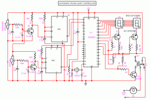
CIRCUIT DIAGRAM

Automatic room light Control with bi directional visitor counter circuit

Automatic room light Control with bi directional visitor counter circuit

RECEIVER CIRCUIT


The IR transmitter will emit modulated 38 kHz IR signal and at the receiver we use TSOP1738 (Infrared Sensor). The output goes high when the there is an interruption and it return back to low after the time period determined by the capacitor and resistor in the circuit. I.e. around 1 second. CL100 is to trigger the IC555 which is configured as monostable multivibrator. Input is given to the Port 1 of the microcontroller. Port 0 is used for the 7-Segment display purpose. Port 2 is used for the Relay Turn On and Turn off Purpose.LTS 542 (Common Anode) is used for 7-Segment display. And that time Relay will get Voltage and triggered so light will get voltage and it will turn on. And when counter will be 00 that time Relay will be turned off. Reset button will reset the microcontroller.Microcontroller based Visitor Counter.

TRANSMISSION CIRCUIT


This circuit diagram shows how a 555 timer IC is configured to function as a basic monostable multivibrator. A monostable multivibrator is a timing circuit that changes state once triggered, but returns to its original state after a certain time delay. It got its name from the fact that only one of its output states is stable. It is also known as a ‘one-shot’.

In this circuit, a negative pulse applied at pin 2 triggers an internal flip-flop that turns off pin 7’s discharge transistor, allowing C1 to charge up through

R1. At the same time, the flip-flop brings the output (pin 3) level to ‘high’. When capacitor C1 as charged up to about 2/3 Vcc, the flip-flop is triggered once again, this time making the pin 3 output ‘low’ and turning on pin 7’s discharge transistor, which discharges C1 to ground. This circuit, in effect, produces a pulse at pin 3 whose width t is just the product of R1 and C1, i.e., t=R1C1.

IR Transmission circuit is used to generate the modulated 36 kHz IR signal. The IC555 in the transmitter side is to generate 36 kHz square wave. Adjust the preset in the transmitter to get a 38 kHz signal at the o/p. around 1.4K we get a 38 kHz signal. Then you point it over the sensor and its o/p will go low when it senses the IR signal of 38 kHz.

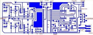
PCB LAYOUT

Click here to go back to List of Projects

BLOCK DIAGRAM OF MICROCONTROLLER BASED MULTI STORY CAR PARKING SYSTEM PROJECT

BLOCK DIAGRAM OF MICROCONTROLLER BASED MULTI STORY CAR PARKING SYSTEM PROJECT

BLOCK DIAGRAM OF MICROCONTROLLER BASED MULTI STORY CAR PARKING SYSTEM PROJECT

DESCRIPTION


OBSTACLE SENSOR SENSING THE INCOMMING CAR
HEADLIGHT SENSING THE OUTGOING CARS
THE STEPPER MOTOR IS THERE FOR MOVEMENT OF LIFT
THREE SENSORS ARE THERE TO SENSE THE POSITION OF LIFT ON EACH FLOOR
LED 1 THROUGH 3 INDICATES ON WHICH FLOR LIFT IS LOCATED
MAXIMUM 9 CARS CAN BE PLACED ON EACH FLOOR GROUND FLOOR FIRST FLOOR AND SEC FLOOR

CLICK HERE TO GO BACK TO LIST OF PROJECTS

INTRODUCTION

Conventionally, wireless-controlled robots use RF circuits,which have the drawbacks of limited working range, limited frequency range and limited control. Use of a mobile phone for robotic control can overcome these limitations. It provides the advantages of robust control, working range as large as the coverage area of the service provider,no interference with other controllers and up to twelve controls.Although the appearance and capabilities of robots vary vastly, all robots share the features of a mechanical, movable structure under some form of control. The control of robot involves three distinct phases: reception, processing and action. Generally, the preceptors are sensors mounted on the robot, processing is done by the on-board microcontroller or processor, and the task (action) is performed using motors or with some other actuators.

PROJECT OVERVIEW

Cell phone operated land Rover

Cell phone operated land Rover,Robot,Moving Vehicle.circuit

In this project, the robot is controlled by a mobile phone that makes a call to the mobile phone attached to the robot. In the course of a call, if any button is pressed,a tone corresponding to the button pressed is heard at the other end of the call. This tone is called ‘dual-tone multiple-frequency’ (DTMF) tone. The robot perceives this DTMF tone with the help of the phone stacked in the robot. The received tone is processed by the ATmega16 microcontroller with the help of DTMF decoder MT8870. The decoder decodes the DTMF tone into its equivalent binary digit and this binary number is sent to the microcontroller.The microcontroller is preprogrammed to take a decision for any given input and outputs its decision to motor drivers in order to drive the motors for forward or backward motion or a turn. The mobile that makes a call to the mobile phone stacked in the robot acts as a remote. So this simple robotic project does not require the construction of receiver and transmitter units. DTMF signaling is used fr telephone signaling over the line in the voice-frequency band to the call switching centre. The version of DTMF used for telephone tone dialing is known as ‘Touch-Tone.’DTMF assigns a specific frequency (consisting of two separatetones) to each key so that it can easily be identified by the electronic circuit. The signal generated by the DTMF encoder is a direct algebraic summation, in real time, of the amplitudes of two sine (cosine)waves of different frequencies, i.e., pressing ‘5’ will send a tone made by adding 1336 Hz and 770 Hz to the other end of the line. The tones and assignments in a DTMF system are shown in Table I.

SCEMATIC OF CELLPHONE OPERATED LANDROVER

Cell phone operated land rover circuit,robot,moving vehicle

Cell phone operated land rover circuit,robot,moving vehicle

CIRCUIT DESCRIPTION

Fig. 1 shows the block diagram of the microcontroller-based mobile phoneoperated land rover. The important components of this rover are a DTMF decoder, microcontroller and motor driver. An MT8870 series DTMF decoder is used here. All types of the MT8870 series use digital counting techniques to detect and decode all the 16 DTMF tone pairs into a 4-bit code output. The built-in dial tone rejection circuit eliminates the need for pre-filtering. When the input signal given at pin 2 (IN-) in single-ended input configuration is recognised to be effective, the correct 4-bit decode signal of the DTMF tone is transferred to Q1 (pin 11) through Q4 (pin 14) outputs. Table II shows the DTMF data output table of MT8870. Q1 through Q4 outputs of the DTMF decoder (IC1) are connected to port pins PA0 through PA3 of ATmega16 microcontroller (IC2) after inversion by N1 through N4,respectively. The ATmega16 is a low-power, 8-bit, CMOS microcontroller based on the AVR enhanced RISC architecture. It provides the following features: 16 kB of in-system programmable Flash program memory with read-while-write capabilities, 512 bytes of EEPROM, 1kB SRAM, 32 general-purpose input/output (I/O) lines and 32 general-purpose working registers. All the 32 registers re directly connected to the arithmetic logic unit, allowing two independent registers to be accessed in one single instruction executed in one clock cycle. The resulting architecture is more code-efficient. Outputs from port pins PD0 through PD3 and PD7 of the microcontroller are fed to inputs IN1 through IN4 and enable pins (EN1 and EN2) of motor driver L293D, espectively, to drive two geared DC motors. Switch S1 is used for manual reset. The microcontroller output is not sufficient to drive the DC motors, so current drivers are required for motor rotation. The L293D is a quad, high-current, half-H driver designed to provide bidirectional drive currents of up to 600 mA at voltages from 4.5V to 36V. It makes it easier to drive the DC motors. The L293D consists of four drivers. Pin IN1 through IN4 and OUT1 through OUT4 are input and output pins, respectively, of driver 1 through driver 4. Drivers 1 and 2, and drivers 3 and 4 are enabled by enable pin 1 (EN1) and pin 9 (EN2), respectively. When enable input EN1 (pin 1) is high, drivers 1 and 2 are enabled and the outputs corresponding to their inputs are active. Similarly, enable input EN2 (pin 9) enables drivers 3 and 4. An actual-size, single-side PCB for cellphone-operated land rover is shown in Fig. 4 and its component layout in Fig. 5.

PCB LAYOUT FOR CELLPHONE OPERATED LANDROVER

Landrover pcb Design

pcb design free

SOFTWARE DESCRIPTION

The software is written in ‘C’ language and compiled using CodeVision AVR ‘C’ compiler. The source program is ed into hex code by the compiler. Burn this hex code into ATmega16 AVR microcontroller.The source program is well commented and easy to understand. First include the register name defined specifically for ATmega16 and also declare the variable. Set port A as the input and port D as the output. The program
will run forever by using ‘while’ loop. Under ‘while’ loop, read port A and test the received input using ‘switch’ statement. The corresponding data will output at port D after testing of the received data.

WORKING

In order to control the robot, you need to make a call to the cell phone attached to the robot (through head phone) from any phone, which sends DTMF tunes on pressing the numeric buttons. The cell phone in the robot is kept in ‘auto answer’ mode. (If the mobile does not have the auto answering facility, receive the call by ‘OK’ key on the rover-connected mobile and then made it in hands-free mode.) So after a ring, the cellphone accepts the call. Now you may press any button on your mobile to perform actions as listed in Table III. The DTMF tones thus produced are received by the cellphone in the robot. These tones are fed to the circuit by the headset of the
cellphone. The MT8870 decodes the received tone and sends the equivalent binary number to the microcontroller. According to the program in the microcontroller, the robot starts moving.When you press key ‘2’ (binary equivalent 00000010) on your mobile phone, the microcontroller outputs ‘10001001’ binary equivalent. Port pins PD0, PD3 and PD7 are high. The high output at PD7 of the microcontroller drives the motor driver (L293D). Port pins PD0 and PD3 drive motors M1 and M2 in forward direction (as per Table III). Similarly, motors M1 and M2 move for left turn, right turn, backward motion and stop condition as per Table III.
CONSTRUCTION

Cellphone operated land rover project

Cellphone operated land rover project

When constructing any robot, one major mechanical constraint is the number there a two-wheel drive or a four-wheel ive. Though four-wheel drive is more complex than two-wheel drive, it provides more torque and good control. Two-wheel drive, on the other hand, is very easy to construct. Top view of a four-wheel-driven land rover is shown in Fig. 3. The chassis used in this model is a 10×18cm2 sheet made up of parax. Motors are fixed to the bottom of this sheet and the circuit is affixed firmly on top of the sheet. A cellphone is also mounted on the sheet as shown in the picture. In the four-wheel drive system, the two motors on a side are controlled in parallel. So a single L293D driver IC can drive the rover. For this robot, beads affixed with glue act as support wheels.

PROGRAM FOR CELLPHONE OPERATED LANDROVER

Source program:
Robit.c
#include
void main(void)
{
unsigned int k, h;
DDRA=0x00;
DDRD=0XFF;
while (1)
{
k =~PINA;
h=k & 0x0F;
switch (h)
{
case 0x02: //if I/P is 0x02
{
PORTD=0x89;//O/P 0x89 ie Forward
break;
}
case 0x08: //if I/P is 0x08
{
PORTD=0x86; //O/P 0x86 ie Backward
break;
}
case 0x04:
{
PORTD=0x85; // Left turn
break;
case 0x06:
{
PORTD=0x8A; // Right turn
break;
}
case 0x05:
{
PORTD=0x00; // Stop
break;
}
}
}
}

CLICK HERE TO GO BACK TO MAIN LIST

BLOCK DIAGRAM OF
ELECTRONICS VOTING MACHINE WITH BALLOT UNIT

Electronic Voting Maching Circuit ckt Diagram

Electronic Voting Maching Circuit ckt Diagram Project

Discription

2X16 LCD DISPLY USED
4X3 KEYBORD USED FOR PASSWORD ENTRY
WHEN CONTROLLER IS CONNECTED TO BALLOT UNIT AND WHEN BUTTON IS PRESSED ON BALLOT UNIT RESPECTIVE LRD GLOWS AND SERIALLY COMMUNICATED TO CONTROLLER TO UPGRADE THE DATA IN EEPROM AS WELL AS DISPLAYED ON LCD.
WHEN YOU WANT TO KNOW THE RESULT OF ELECTION CONNECT THE CONTROLER TO PC AND BY PRESSING THE KEY YOU CAN KNOW THE RESULT
ON MONITOR OF PC AS WELL AS SAVE THE FILE IN PC .

Click Here to Go Back To Complete list of Projects

Electronic voting Maching Project, Electronic Voting Maching Circuit, Electronic Voting Maching Free Project, Microcontroller based Electronic Voting Machine.